Different Types of Sensors
Voyager FDS Sensors
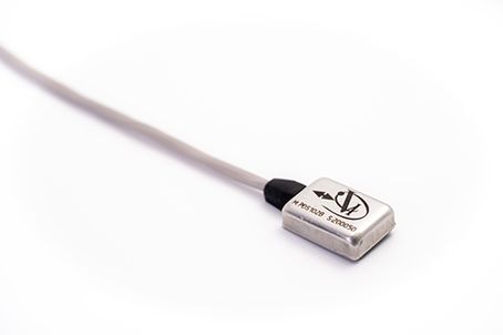
The Voyager FDS Sensor is a specifically designed dynamic strain sensor meant to be used in an industrial setting to monitor the health of fluid film bearings supporting rotating machinery. Using strain to monitor fluid film bearing health was granted a United States patent in 2017. Using strain measured on a fluid film bearing in order to diagnose common machinery faults, such as unbalance and misalignment, was granted a United States patent in 2020. Red Wolf Reliability is the assignee on both patents.
There are a large number of strain sensors available on the market including metal foil gauges, piezo-resistive strain sensors, piezo-electric strain sensors, and optical strain sensors. The aforementioned patents cover all types of strain sensors. All can be dynamically sampled in order to give signals useful for machinery analysis. However, the metal foil and piezo-resistive sensors require an intricate installation including electrically balancing a wheatstone bridge. The Voyager FDS sensor is a piezo-electric strain sensor which does not require this complicated installation.
The sensor uses piezoelectric material for the sensing element and is powered by standard IEPE power. Typical sensitivity is approximately 50 mv/με. The application of this technology is so new that many vibration instrumentation vendors have not yet modified their software to accommodate the new measurement units. If this is the case, simply set the sensor up as an IEPE accelerometer with the assigned sensitivity and measure “acceleration” so as to not integrate the microstrain measurement. Until the vendors make software modifications (if they already have not), the analyst will have to know that the acceleration units displayed are actually microstrain. Effectively microstrain is dimensionless. More rigorously, microstrain is measured as a change in length of a body (whether in tension or compression) divided by the total length of that body (ΔL/L). Typical strain levels to expect will range from 1 to 50 με depending on the machine.
Accelerometers
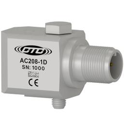
When the Lally brothers made the move to integrate an amplifier into a piezoelectric accelerometer in the early 1970’s, it revolutionized the vibration condition monitoring industry, especially for rolling element bearing machines.
Previous accelerometers required external amplifiers, low noise short cables, and were not very robust. Creating the ICP accelerometer facilitated route-based vibration monitoring.
And while these sensors are an excellent solution for rolling element bearings, they are not ideal for fluid film bearings. Some reasons for this include:
- Accelerometers directly measure the acceleration of the vibrating surface. Typically, a machine that utilizes fluid film bearings has a relatively heavy casing compared to the rotor it houses. So when a “small” rotor transmits acceleration to the large housing, standard momentum theory dictates that the resulting acceleration is small. This makes an accelerometer insensitive to accelerations in the rotor.
- A fluid film bearing has anisotropic stiffness, meaning that it is stiffer in the Y-axis than it is in the X-axis. This is because the high-pressure wedge focuses the load to be carried mostly in one concentrated location. It means the typical vibration analysis rules for comparative amplitudes on rolling element bearings – which do have isotropic stiffness - are not applicable.
- A fluid film bearing can have as much as ten times the damping that a rolling element bearing does. This means that high velocities are significantly diminished by the time they reach the bearing casing. Since most condition monitoring procedures with an accelerometer integrate the signal to velocity, this makes for a severe disadvantage for health monitoring.
- Even though oil is considered an incompressible fluid, when additional load is applied to the bearing, the shaft displaces increasing eccentricity while reducing the minimum fluid film thickness. This causes a change in stiffness which is not linear. So, a change in vibration of the rotor does not produce a proportional change in the acceleration of the housing.
Even with these shortcomings they are used quite often for fluid film bearings. However, it takes considerable experience and trending to understand malfunctions that are more easily diagnosed with other technologies.
Eddy Current Probes
Just as revolutionary as the integrated amplifier in the accelerometer was employing an eddy current probe to detect shaft vibrations in a fluid film bearing. This was applied by Bently Scientific in the 1960’s. Once this idea became popular, Don Bently renamed his company to Bently Nevada and moved it to Minden, Nevada. Up until that point, shaft riders were the state of the art.
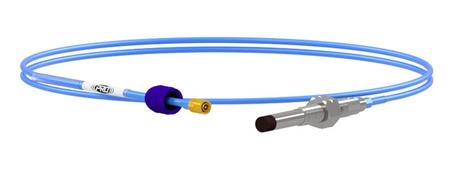
Using and eddy current probe to detect shaft position makes it a proximity probe. This is a transducer that measures displacement as its native unit. The primary components include an oscillator which generates an eddy current, and a detector which senses the change in both the DC and AC voltages.
While the case mounted accelerometer measures absolute vibration levels, the proximity probe measures shaft displacement relative to the bearing housing. Relative motion between a shaft and a magnetic field generates a phenomenon called eddy currents. Eddy currents create electromagnets within the magnetic field. Changes in the proximity of either the magnetic field or the shaft, will give a proportional change in eddy current flow, which then gives a corresponding change in both amplitude and phase of the current.
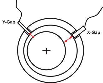
Usually two proximity probes are mounted for each bearing—each installed 45 degrees from vertical. This installation places two sensors 90 degrees apart from one another. These probes are typically labeled X to Y in a counterclockwise direction when looking at them from the drive end of the machine. Figure 44 shows a typical proximity probe installation. The frequency range on most proximity probes is as high as 120,000 CPM.
Proximity Probe Considerations
There are a few considerations with respect to using proximity probes for fluid film bearing monitoring. The first is that there are two distinct signals from the system: AC vibration portion and a DC gap portion.
The AC vibration portion gives the analyst a view of the shaft vibration relative to the bearing housing. This vibration is measured in displacement units. The DC gap portion tells the analyst the distance from each probe to the surface of the shaft. If the clearance circle is known, then this information is very powerful in that it can give the analyst a direct measure of attitude angle and eccentricity. Figure 1 presents this gap measurement.
Figure 1 - Proximity Probe Configuration
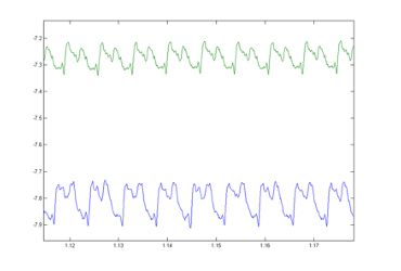
Figure 1 presents the raw signals from an X and Y probe. Note that they are centered on two different zero, or bias signals. The top signal is centered at -07.28 volts. The lower signal is centered at -7.83 volts. If the proximity probes are 200 mv/mil sensors, then the sensor displayed on the top trace has a gap of (7.28/0.2) of 36 mils and the sensor displayed by the bottom trace has a gap of (7.83/0.2) 39 mils.
Figure 2 - Proximity Probe Raw Signals
If the typical bearing clearance is 1.5 mils per inch of shaft, then a gap voltage of 39 mils would imply a shaft with a massive diameter. But it should be noted that proximity probes are mounted within an internal countersink and this gap is measured from the tip of the probe mounted well within the countersink. The user would have to know the calibration set points, the clearance circle, and this gap value in order to locate the shaft.
Now the AC, or alternating, portion is examined. If the top trace in Figure 46 ranges from -7.22 to -7.33 volts then the AC portion is the difference in the range. So, in this case the range is 0.11 volts which equals a peak to peak maximum AC portion of (0.11/.2) 0.55 mils.
The second consideration is that a proximity probe gives a relative vibration measure. So, if the bearing housing is being influenced by outside forces, it could skew the analyst’s perspective on the source of the excessive vibration. If a trend is rising, the question will be is it rising because the shaft is vibrating more or is it because the casing is moving more.
A third issue is that the target area for the proximity probe must be prepared properly with the correct surface finish. Scratches in the finish will be perceived as movement and a misdiagnosis may occur.
A final consideration is runout correction. Any mechanical runout will have to be compensated or the system will perceive that runout as vibration and again, misdiagnosis could occur. Any electrical runout, which is usually a result of a magnetized section of the shaft, will also need to be compensated. Correcting both of these is key to having accurate proximity probe data. This process is called runout compensation. Most software can apply this correction, once collected, to any current reading.
